Managing Transformations
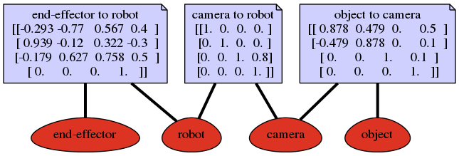
It is sometimes very difficult to have an overview of all the transformations that are required to calculate another transformation. Suppose you have a robot with a camera that can observe the robot’s end-effector and an object that we want to manipulate. We would like to know the position of the end-effector in the object’s frame so that we can control it.
We can organize transformations in a graph like the one shown in the figure below. Each frame represents a vertex (node) and each transformation an edge (connection). Edges in these graphs are directed, but we can create an edge in the opposite direction by inverting the transformation. If we want to compute a new edge indicated by the dashed red arrow, we have to use known transformations, that is, we compute the shortest path through the undirected graph, concatenate transformations along the path, and invert transformations if required as indicated by the solid red arrow.
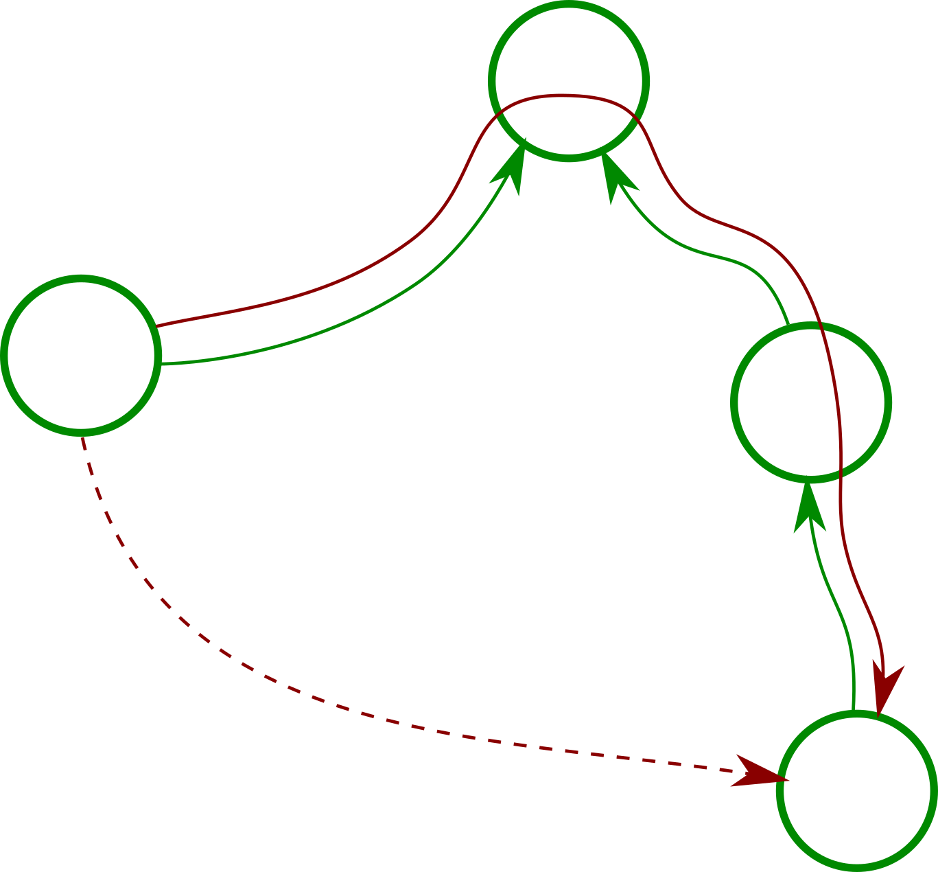
Example of a graph representing transformations that connect frames.
The TransformManager does this for
you. For the given example, this would be the corresponding code
(see also: Transformation Manager).
tm = TransformManager()
tm.add_transform("end-effector", "robot", ee2robot)
tm.add_transform("camera", "robot", cam2robot)
tm.add_transform("object", "camera", object2cam)

ee2object = tm.get_transform("end-effector", "object")
We can also export the underlying graph structure as a PNG with
tm.write_png(filename)
A subclass of TransformManager is
UrdfTransformManager which can load robot
definitions from URDF files.
The same class can be used to display collision objects or visuals from URDF
files. The library trimesh will be used to load
meshes. Here is a simple example with one visual that is used for two links:
URDF with Meshes.